Peter - A photo would be impossible, since the system has parts running behind my entire system, the entire length of the room, since the controller is on one end of the room, the reservoir on the other...
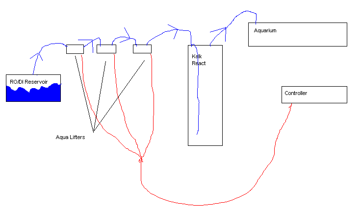
Please excuse the HORRIBLY bad sketch, but here's a basic layout of it...
Blue lines are water, red are electricity.
alt="">
Hey, I never claimed to be an artist!
The RO/DI reservoir has a mechanical float valve in it, and is plumbed directly into my RO/DI system so it stays fulls.
I didn't show it in the diagram, but there are 4 electric float switches wired in series (So that all 4 have to register "low" for the circuit to be energized) between the aqualifters and the controller. The controller is the "master" control so to speak, if the pH is too high, it cuts power to the float switches, which in turn cuts power to the aqualifters. If the pH is in spec, then the float switches are energized, and the decision to energize the aqualifters is in their hands. If all 4 float switches read low, then the circuit to the aqualifters is energized, and the topping off is allowed to occur...
I hope that makes sense... if not lemme know what part doesn't and I'll try to clarify...
 does have a GEO 624. I want to supplement to keep the pH up during the night mainly and my corals respond well to topping off with kalk.