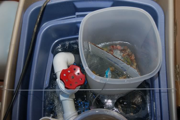
Here is a little better explanation of the closed loop. As I said before, this is not my design, it was modeled after Marc's 29g closed loop.
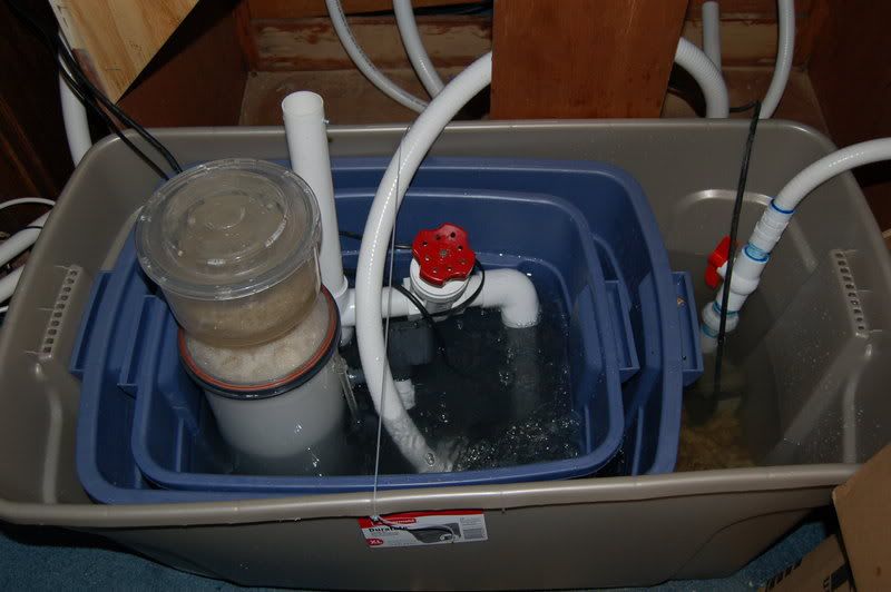
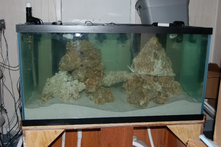
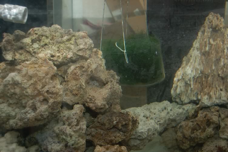
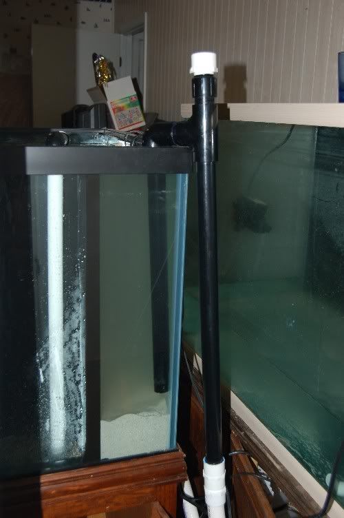
This is the intake.
 alt="">
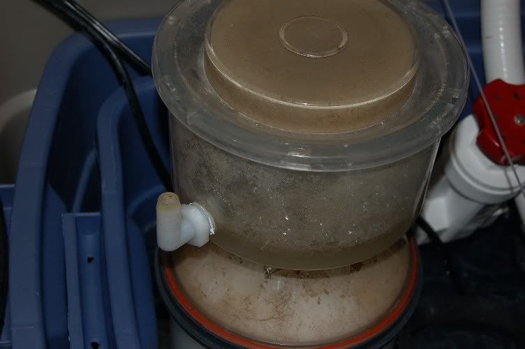
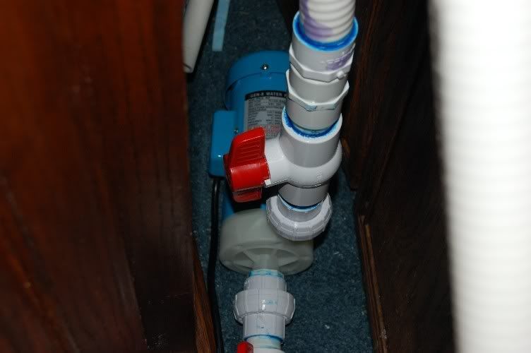
It is first started by removing the white (soon to be painted black) threaded cap. Then I had to close one of the ball valves on the pump.
 alt="">
Next I poured water into top where the cap was until the pipe was full, this removed all the air out of the intake side. Next I put the cap back on. BTW all threaded joints have 3 layers of teflon tape. Lastly I opened the ball valves and turned the pump on. Within a few seconds the pump pulled any small remaining amounts of air through the pipes.
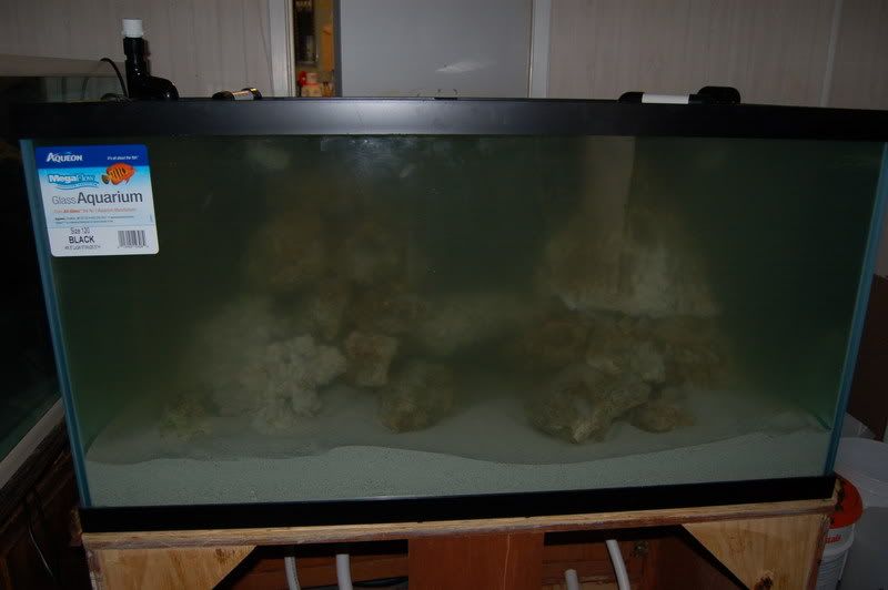
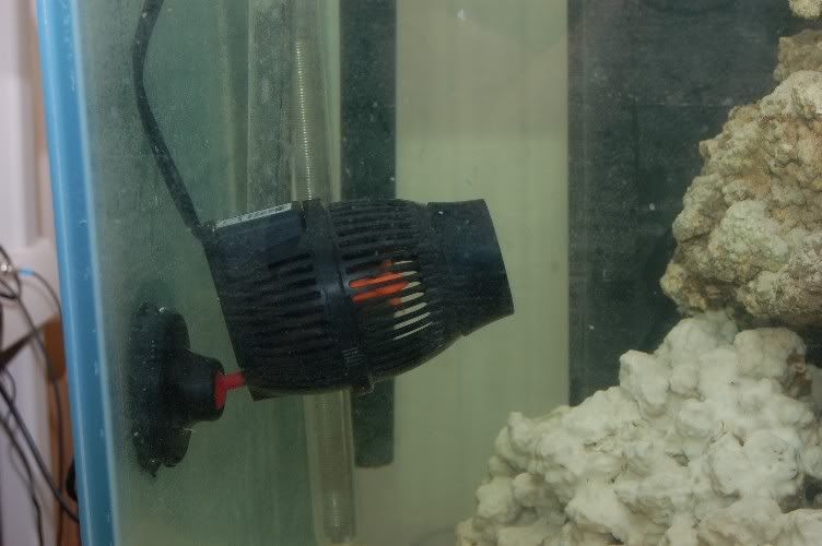
After the water enters the pump it goes through a few feet of spaflex and the plumbing splits into 2 3/4 inch legs. Each of these comes back into the tank at the return bulkheads, and is plumbed over the top of the overflow tower. At first I had a penductor at the ends, but I have them off right now due to the sand issue.
This is the intake.
It is first started by removing the white (soon to be painted black) threaded cap. Then I had to close one of the ball valves on the pump.
Next I poured water into top where the cap was until the pipe was full, this removed all the air out of the intake side. Next I put the cap back on. BTW all threaded joints have 3 layers of teflon tape. Lastly I opened the ball valves and turned the pump on. Within a few seconds the pump pulled any small remaining amounts of air through the pipes.
After the water enters the pump it goes through a few feet of spaflex and the plumbing splits into 2 3/4 inch legs. Each of these comes back into the tank at the return bulkheads, and is plumbed over the top of the overflow tower. At first I had a penductor at the ends, but I have them off right now due to the sand issue.